
By Gary Bunzer
October 2019
50 Vs. 30
 My RV is set up for 30-amp service. My neighbor told me it is better to get a 50-amp adapter and use the 50-amp shore power connection than to use the 30-amp socket. Is there a good reason to do this? Is it safe?
Charles Wehland
Via email
If your RV is configured with a 30-amp electrical system, there is no benefit to plugging into a 50-amp receptacle. In fact, to do so requires a 30-to-50 adapter, as you mentioned, which simply adds another mechanical connection to the system. Any type of additional connection is yet another potential point for moisture to enter. Even worse, the connection may loosen as the connecting points become worn from use. The result will be added heat and resistance, and neither is good for the flow of electricity. Your RV still will be limited to a maximum of 30 amps of total current flow. So, it is always best to plug into a receptacle with the same rating as your shore cord, thereby keeping the mechanical connections to a minimum.
Reduced Waterflow
We have a 2018 Holiday Rambler Vacationer motorhome. We do not have a steady source of hot water while connected to city water unless we either run the water pump or we don’t use the reducer on the water line. The dealer and manufacturer both blame the pressure at the campground. That doesn’t make sense to us since other campers do not have this problem. We have had this issue since buying the motorhome new. Any suggestions?
Deb Seda, F483941
Sanford, Florida
Your problem, believe it or not, is fairly common in RVs. There are a few possible causes, but the most likely, in my opinion, is a failed or faulty check valve (backflow preventer), typically attached at the rear of the water heater in either the cold inlet or the hot outlet fitting of the heater. Usually the RV manufacturer installs it as part of a bypass assembly for the water heater.
Another possible culprit, high on the list of suspects, is a failed bypass valve itself, also positioned at or near the rear of the heater. Many today are made of plastic, unfortunately. If a replacement is necessary, use a metal one. Hot water running through a plastic valve may warp the body over time, causing the valve gate to become blocked and unable to fully open or close. Also, the seals inside the valve may have become dislodged because of the heat/plastic combination. This, too, can cause low pressure on the hot side.
A third possibility is a mineral deposit buildup in either of the valves or in the distribution tubing. This is unlikely in your case since your coach is relatively new. During construction, all RVs are tested at between 80 psi and 100 psi, so it’s probably okay to remove the inline regulator for a quick test to determine whether that component is at fault.
In addition, there’s an outside chance that a section of tubing is kinked in the hot distribution system at or near the back of the heater. Inspection of the tubing can eliminate or confirm this.
But very likely the problem, which I see frequently, is a failed bypass valve or backflow preventer at the water heater. Probably your biggest challenge is gaining access to the very rear of the water heater from inside the motorhome. Upon gaining access, most handy RV people can replace a valve or a backflow preventer using common tools. Of course, any certified RV technician can do it also. I further recommend an adjustable pressure regulator — equipped with a pressure gauge — so you can adjust the campground pressure if need be, as well as measure the actual pressure being delivered to the RV from that spigot.
Zoning Out
After replacing the air conditioner (we have a Dometic), I’m having problems getting Zone 3 on my thermostat to reset. Any ideas?
Robbie
Via email

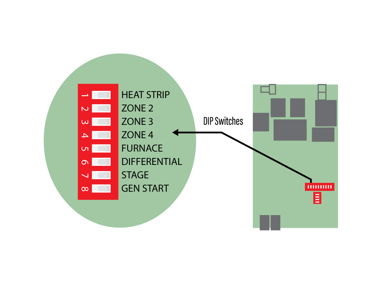
A Dometic Comfort Control Center dip switch diagram.
It sounds as though you may have an issue with the Dometic Comfort Control Center (CCC). The troubleshooting procedures are somewhat complicated, but if you’re handy with a digital multimeter (DMM), here are some procedures you can perform. Keep in mind it may be something better left to professionals. For one thing, this requires some testing on the roof at the air conditioner.
To check the CCC, measure the incoming DC voltage and polarity at the main control in the upper unit on the air conditioner at the red (positive) and black (negative) conductors. The control voltage should be 10 to 16 volts DC. Check for voltage on both sides of the 3-amp fuse at the control board as well. This proves the fuse is indeed healthy.
Check the output voltage of the thermostat at the telephone wall jack. One end of the cable is plugged into the air-conditioner power module/electronic control box RJ-11-6C4P jack. The CCC end is plugged into the telephone wall jack. Use a DMM to measure the DC voltage between the red and black terminals.
To check DC voltage at the thermostat, remove it from the mounting bracket. On the reverse side of the thermostat, above the RJ-11-6C4P jack, are four solder points where the DC input can be measured.
If the proper voltage is measured at the control board, and control voltage at the thermostat exists, do a system reset at the CCC. I know you’ve already tried a reset, but follow these instructions one more time:
*Turn the on/off switch to “off.”
*Simultaneously depress and hold the Mode and Zone buttons while turning the on/off switch to “on.” The letters FF should be displayed on the monitor until the Mode and Zone buttons are released. If the letters EE appear when the buttons are released, do the reset again. If EE keeps coming back, there is a communication problem with the cable itself.
*When a dual inline package (DIP) switch is turned on or off after the initial configuration, a system reset will need to be done before the CCC will recognize the updated selection. Any time a component is added or removed, it’s best to do a reset. The comfort control thermostat itself cannot be repaired. If it’s faulty, it will have to be replaced.
Also, if the following items test okay, replace the CCC.
*DC voltage is correct at the control board and thermostat.
*No other DC appliances are hooked to the DC power conductors running to the CCC.
*The DC volts powering the control system could have a strange AC sine wave creating erratic operation or behavior. Perhaps try a different DC power source, do a reset, and test.
*Control board, temperature sensors (with the freeze-remote-ambient unplugged) all test okay.
*Cable assembly tests okay.
*If the cable runs are not longer than 75 total feet, the configuration is correct.
The CCC can operate up to four units, provided the configuration is correct. The configuration for Zone 1 is all DIP switches “off.” On all units, the cold control on the evaporator fins must be plugged into the blue P5 connector on the board, and the sensor must be inserted securely in the evaporator coil. If a remote sensor is used for that zone, it plugs into the white P4 connector. The control box or power module connects to the CCC by a telephone-type cable. If more than one unit will be operated off the CCC, a second telephone-type cable is needed. Both telephone cables are plugged into the control box or power module for the first unit. The second cable is routed to the control box or power module for the second unit. The DIP switch for Zone 2 must be turned on. Each additional zone (up to four total zones) requires only the DIP switch for that zone number to be turned on. Be sure your Zone 3 is “on.”
I realize these steps may be beyond the typical handyperson. If all else fails, it might be time for a trip to a certified RV technician. Or contact Dometic customer service for assistance, and have your exact model and serial number handy.