The SeeLevel II tank monitoring system provides users with a more realistic indication of RV holding tank levels.
By Mark Quasius, F333630
June 2012
Motorhomes have been equipped with holding tanks for fresh water and black or gray water since the first coaches were built. And the monitoring systems used to keep track of the fluid levels in these tanks haven’t changed much during the past 40 years. Until recently, tank monitoring systems were limited to four or five internal sensors connected to a remote display with a series of panel lights or LEDs to indicate “Empty,” “1/3,” “2/3,” or “Full” tank levels.
The problem with these sensors is that they are notoriously inaccurate and susceptible to fouling, which will give false readings, most often reporting the tank as full when it’s not. Various methods for cleaning the tank sensors have been tried, from chemical additives to tricks such as loading the black tank with ice and driving the motorhome to try to knock the buildup off the sensors. Yet none of these solutions provides a permanent — and sometimes not even a short-term — solution, and the false readings continue.
Even when these sensors are clean and operating as designed, the level of accuracy is questionable. For instance, if the water level in the fresh tank is just above the two-thirds sensor, the display will show “2/3.” But the minute you run the kitchen faucet, the water level will drop below the two-thirds sensor, and the tank monitor will report the fresh tank as only one-third full, when really it’s still almost two-thirds full. In the same manner, the gray water tank display may show “1/3,” but the true tank level may be just beneath the two-thirds sensor. As soon as you begin your morning shower, the water level rises, and by the time you’re finished, the tank is full and the shower drain is backing up and filling the shower stall with water. These are just a few of the drawbacks to having an internal tank sensor system that measures at one-third intervals.
Fortunately, tank monitoring technology has improved in recent years. Garnet Instruments Ltd. has supplied tank monitoring systems to the petroleum industry since 1993. A subsidiary of the company, Garnet Technologies Inc., uses the same technology as the basis for its SeeLevel II (709 Series) tank monitoring system for RV applications. The system offers benefits not possible with internal sensor systems. The SeeLevel II uses a sensor strip that is applied to the outside of the holding tanks. This system continuously monitors along the length of the strip so no gaps in coverage exist and accuracy is achieved. And because the sensor strip attaches to the outside of the tank, it isn’t susceptible to fouling.
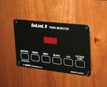
The SeeLevel II monitoring panel is another huge step forward. It consists of a digital LED readout that displays the tank level in 2 percent increments. With this system, when the tank is 62 percent full, the number 62 is shown on the LED display rather than the “1/3” LED readout on a typical internal sensor system.
Several motorhome manufacturers are including the SeeLevel II as standard equipment in new motorhomes, and it also can be added as an aftermarket upgrade. It can be installed by just about any RV service center or purchased directly from Garnet Technologies or a number of RV supply outlets and installed by the owner.
The following steps detail the installation I performed in my 2007 Allegro Bus.
Planning Your Installation
Before beginning the installation, you have a decision to make. You can remove the existing monitor panel and replace it with the SeeLevel II display, or you can leave the existing monitor where it is and locate your new SeeLevel II panel somewhere else. If you replace the old panel with the new display, you can reuse the existing wiring from the old in-tank sensors. If you relocate your panel, it will be necessary to reroute the existing wires or run all new wiring from the new sensors to your desired display location.
For my installation, I decided to abandon the existing panel and locate the SeeLevel II display in a better spot. The original monitor display was part of a larger panel that included switches for the slideouts, the Hydro-Hot system, and other features. It was located in a cabinet above the driver’s seat, which wasn’t handy while living in the motorhome. I decided to install the new SeeLevel II display in a convenient location next to the thermostat and other electrical controls in the hallway. That meant I needed to run new wiring.
 Sensor Strips
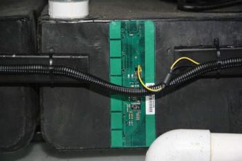
The standard SeeLevel II sensor strip measures 12 inches long. The electronic components are arranged in 1.5-inch groups, and the strips are designed to be trimmed with a razor knife in 1.5-inch increments so that the sensor length matches the tank height. Once cut to the proper length, they will automatically calibrate to the tank size. Each sensor strip includes a series of transmitters on one side and a series of receivers on the other side. An electromagnetic wave is transmitted through the tank, and when it passes through the tank’s contents, the signal is refracted back to the receiver side of the sensor strip. In a vacant area of the tank the signal is not refracted; therefore, the tank level can be accurately determined by the electronics on the sensor strip. For tanks that are taller than 12 inches, two sensor strips can be connected and programmed to work as one continuous unit.
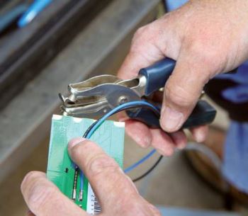
Begin the installation by preparing the tank sensors. All of the holding tank sensors are daisy-chained together and communicate with the display panel through one common wire. Each sensor is given a unique identity with a set of labeled tabs at the very top of the sensor strip. You simply take a paper punch or razor knife and remove the tab that identifies the position of that sensor (fresh water, gray water, or black water tank). Then tie all three of the yellow wires together and connect them to the display unit. Do the same with the three ground wires by connecting them to a good common ground connection. In some cases, it may be hard to find a good ground connection, and some coaches may have grounding issues that affect the accuracy of the signal. If you find either of these to be a problem during your installation, you can run a ground wire directly to the display unit and tie in with the display unit’s ground connection. If you are reusing the existing sensor wires, you can use one of them for your main feed and another for the ground return.
 The sensor strips come with 3M adhesive with peel-off backing already applied. Prior to attaching the sensor, it’s important to clean the tank surface with acetone or rubbing alcohol to eliminate any oil or film that may prevent proper adhesion. Then simply remove the backing and position the sensor on the tank. The adhesive will bond in approximately 15 seconds.
Your tank height might not divide out into exact 1.5-inch increments, so there may be instances when the sensor won’t cover the full range of the tank. In that case you can shift the sensor to the top or bottom a bit to improve accuracy. In the case of a fresh water tank, it’s more important to know when you are approaching empty, so it’s best to locate the sensor flush with the bottom of the tank. With the black or gray water holding tanks, you want to know when they are getting full, so it’s preferable to locate the sensor at the top edge of the tank. It’s also useful to place the sensor as close to the center of the tank as possible rather than at the far front or rear of the tank. That way you’ll have a more accurate reading if your coach is parked in an unlevel spot.
Once the sensor strips are applied to the tank, you won’t be able to move them should you change your mind. So, if you aren’t sure whether you’ve chosen the best location, leave the backing on the adhesive and temporarily attach the sensors using masking tape so that you can shift their position if needed. Once you’ve verified that they are reading the way you want, remove the tape and permanently apply them using the 3M adhesive backing.
The Display Module
The display module requires 12-volt-DC fused battery power and a good connection to ground. If you choose to run a ground connection line from the sensors, then that wire also will be spliced into the display’s ground wire. The SeeLevel II system doesn’t draw much power, so #18 wiring is all that’s required.
Mounting the display requires cutting a small rectangular hole in the dash, wall, or other surface chosen for the unit. Four small screws are used to mount the display panel to that surface. Once your wiring connections have been made, all you need to do is plug in the panel, secure it using the four screws, and you’re all set.
To operate the display, simply press the desired button on the membrane panel. The tank level will be shown in the two-digit LED readout display and will remain illuminated for a few seconds. You can toggle quickly through the buttons to view all of your tanks, or if you want to leave a specific display on for a longer period of time, press and hold the desired button for two seconds and the display will remain active. The correct level will be shown and updated in real time so you can see how fast the tank is filling or draining. Don’t worry if you forget to turn off the display. After a few minutes the number will disappear to conserve battery power. Pressing the button a second time will restore the display and reset the timer. Diagnostic capabilities also are built into the module and are fully described in the owner’s manual.
Most SeeLevel II displays also can monitor your propane tank. Propane tanks generally contain a float-type sending unit that employs a variable resistor connected to the existing monitor panel via a single wire. This measures the resistance in the tank sending unit to register how much propane is in the tank, which illuminates the proper LEDs. The SeeLevel II display utilizes the same wire, but it will report propane levels in 2 percent increments, so you’ll have more accurate information as to just how much propane remains in the tank. All of the wires plug into a pigtail, so it’s an easy task to use crimp-style butt connectors to attach the pigtail to existing or new wires.
 Options
SeeLevel II displays are available in a number of models for both three-tank and four-tank configurations. Models are also available with switches to operate water pumps and water heaters. Other models include RV-C network communications to interface with a data buss, SilverLeaf monitor, or Monaco’s Aladdin system. One recent introduction is an alarm version that includes analog switch outputs triggered by user-adjustable alarm settings. They can be implemented to warn of any tanks that are close to full or empty.
One possible use is for macerator toilets installed in rear-bath floor plans. Typically, a float switch is used to prevent operation of the macerator should the black tank fill to capacity. However, many people have found this float switch to be unreliable. With an external SeeLevel II sensor and alarm panel, users have a more accurate safety feature for the macerator toilet.
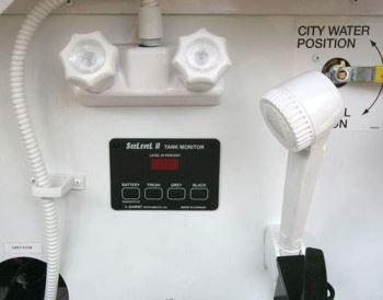
It’s also possible to add more display panels to the SeeLevel II system in a separate location. In my case, a smaller panel was added in the basement water service bay so that I can monitor the tank levels from that area rather than having to go inside the coach to check levels when servicing the tanks. This has been a popular configuration for motorhome owners.
Benefits
The SeeLevel installation has been one of the best upgrades I’ve made to my Allegro Bus. The system wasn’t expensive — systems range in price from $225 for the base model to $499 for model 709A-RVC, which includes four alarms and Canbus communication — and was a fairly easy installation, which many motorhome owners can perform as a do-it-yourself project. It has eliminated any sensor fouling issues and has provided accuracy never before possible when determining holding tank levels. Overall, I couldn’t be more pleased with the results.
Garnet Technologies Inc., 125 M&M Ranch Road, Suite 8, Granbury, TX 76049; (877) 668-7813, (817) 578-8601; www.rvgauge.com

